
The SSB install was a multiple step process for us. Step 1 was to mount the transceiver (the radio) at the nav station, run wires to the antenna tuner which is mounted in the very back of the boat in a lazarette near the stern, run power to the radio and connect it to the modem.
Here is the finished product so you can get a sense of the goal:
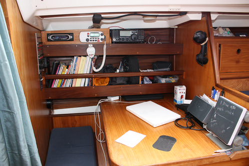
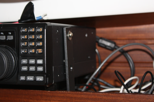
Our radio is big and unlike some other big radios it doesn't have a remote front plate which would allow us to mount the bulky part somewhere out of the way and put the front plate at the nav station. This wasn't much of an issue for us as we would have ended up putting the bulky part at the nav station anyways. I can tell you for certain that having a smaller radio would have made it a lot easier.
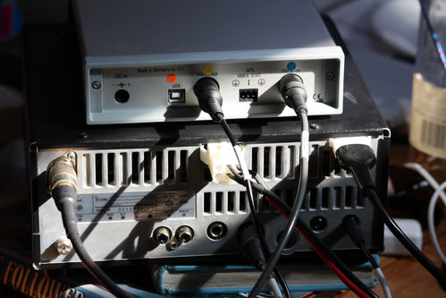
The other issue is that the plugs on the back of any SSB are big and you have to take into account their size before mounting the radio. Here is the back of the SSB and the modem with all of the various connections:
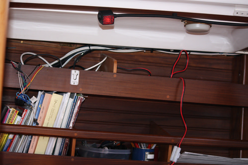
The wires that connect the radio to the power and the antenna tuner are run through the ceiling (as are most wires in our boat, this keeps them out of the way and less likely to be sitting in standing water). Thus, the first step was to pull out our stereo, VHF radio and the woodwork that was added to mount those.
Then I disconnected the wires from the transceiver, removed all of the ceiling panels in the aft cabin, removed all of the stuff in the back lazarette and then ran the wires from the nav station all of the way to the back of the boat. After 30 minutes of collecting fiberglass splinters it occurred to me to wear gloves.
There is a standard mounting bracket for our radio which, of course, does not work in the space we have for the radio. We bought some metal shelf brackets which were the perfect height to bolt to the shelf underneath the radio and screw into the mounting holes already built into the side of the radio. Of course, the brackets were too long to fit underneath the radio so Carol cut a section off of each bracket. I painted these with black rust paint. I also took three pieces of marine grade plywood, glued them together and painted them to use as a block to provide support for the back of the radio.

Now, another fun part. How do you drill holes in the shelf? The drill won't fit on the top and will only kind of fit underneath the shelf. After some choice swear words I managed and was able to bolt the brackets through the shelf (with washers to distribute the weight on the wood).
Finally, I wedged the radio into position. It barely fits which is perfect because it has no where to wiggle to. It is wedged up to the ceiling at the back with the block and is bolted on each side to the brackets which are bolted to the shelf and the front of the radio rests on the shelf front. It is solid. Even if we get rolled, it should stay put.
And voila - it's mounted. Well, that is, after getting everything back together, realizing I had knocked a connection on the CD player loose, fixing that, and putting everything back together again.
Next stop, the tuner.


What make and model of radio is that, Livia?
ReplyDeleteI "hope" our install goes a little easier!
Mike
Liva,
ReplyDeleteI do hope that you are going to put a few "fair-rite" chokes on the cableing between the transceiver and the modem. This is really essential to get everything to work without having any RF feedback. I would also recommend using them for all cableing to your computer as well. I used them on all connections going to the radio as well (power, antenna, modem).
Well good luck & hope to hear you on the GNBN when we return to the NW in June.
KF7GFM & WA7PIB
Nicely done!
ReplyDeleteBut big? That radio is a lot smaller than our old TS440S!
Bob
WA9BVE
Hi Kate & Carl,
ReplyDeleteOur Fair Rite plan is to install them on the control/audio cables to the modem (4 total, one on each end of each wire) and the two wires from the computer to the tuner (control and coax). We have 6 which came with our used package and were going to buy the additional.
How does that sound to you?
- Livia
Looks good, Livia. What are you using for a ground plane? I think my weak link may be the 1.5" wide copper ribbon that I used to connect my tuner to my Dynaplate. I'm gong to run another strip or two alongside it and see if that will finally get me "out".
ReplyDeleteOh and I'm with Bob who said "Big?" You ought to take a gander at my iCom M710. What a beast!
Hi Steve & Lulu,
ReplyDeleteWe are starting out our ground plane with a single copper strap (3" wide) to a thru hull (with capacitors). We will add in our water tanks after that if we need them.
Livia
Liva,
ReplyDeleteI ended up using a lot more fair-rite chokes on our HF system than what came with the connection kit. I used quite a few on the computer and HF radio (mouse & keyboard leads, monitor leads both signal & power, GPS lead into computer, power lead & coax to the HF radio, power lead & coax to the tuner). As usual, I was probably approaching overkill. If you have any problem with stray RF in any of your electronics this might help out.
I got the extra ones (my kit came with 6 as yours did) from Allied Electronics as the pricing is WAY better than any marine dealer(this is where they buy them to sell to you). Just be sure to use the ones made from "type 31" material.
And your radio is very small compared to the ICOM M710 that we have aboard MOM.
Thanks!
ReplyDelete